(Original version)
To read about an updated version of this filter, click here.
The problem:
In late 2010, Barry, G8AGN and his friend Gordon, G0EWN were running tests using optical, through-the-air voice links near Sheffield, England. Being a fairly large city, it was difficult to find a path that was completely devoid of extraneous sources of light so the received audio - in at least one direction - had a fair amount of AC hum from mains-powered urban lighting. While the hum didn't completely cover the speech, it made it challenging to understand..
Listen to a portion of this exchange here:
- Audio
file: G0EWN at Roper Hill being
received by G8AGN at Harpswell via a 66km optical path.
Note that this was recorded acoustically - that is, a
microphone placed near the speaker - hence the noise of
passing vehicles on the nearby roadway! (2:46,
MP3 format, 1.9 Meg)
- The use of optical filters to reduce/remove light from other sources. If a fairly narrowband optical filter were used on the receiver, "off-wavelength" light could be rejected - but such filters are quite expensive, they can be difficult to implement on a very simple optical system1, and some may not even be usable with the relatively wide spectral width of LED-based emitters. An alternative would be to use theatrical "gels" chosen to pass the desired wavelength with minimal attenuation while rejecting some of the dominant wavelengths of the light pollution. For red LEDs (615-650 nanometers) the Roscolux "Fire" (#19) theatrical "gel" filter (or its equivalent) has been found reduce the effects of both high-pressure sodium and mercury vapor light pollution by about 6dB while minimally impacting the desired signals.
- Narrower beamwidth. The use of a large-aperture lens coupled with the smallest-area photodetector practical can narrow the field-of-view of the detector allowing greater discrimination of off-axis, interfering sources. This can be accomplished with a photodetector that has an active area about the same size as the "blur circle" 2 of the lens system or by masking off a larger detector to a size that is slightly larger than that of the lens system's blur circle.
- Slightly off-point the receiver to better-reject the
noise source. Even if the desired signal is
reduced, the net effect may be an overall improvement
of the signal-noise ratio is the interfering light source is
farther off-point than the desired signal.
- The use of a subcarrier on the link instead of baseband. This method simply shifts the audio so that it is conveyed at a frequency above where the majority of mains-induced interference dominates and this works as long as the receiver itself isn't being overloaded by the light! Unfortunately, use of higher frequencies has the result of reducing effective receiver sensitivity as many of the most-sensitive detectors rapidly drop off with increasing frequency - but if there is sufficient excess link margin, this can work! The need for extra gear (for generation and demodulation of the subcarrier) complicates the overall setup, however.
 |
If, after you have tried optical methods of minimizing hum (e.g. filters, beamwidth, and off-pointing), another means to minimize the effects of hum from lighting would be to filter it from the received audio - provided that the influence of the light that caused the hum isn't actually overloading the receiver itself! If the receiver is overloaded by extraneous light, desensitization and/or distortion may result - in which case neither audio filtering or the use of subcarriers may help much! Assuming that the receiver isn't being clobbered, filtering of hum is possible since the frequency spectra of such interference is typically very stable and well-defined.
The individual frequency components in the hum (or buzz) from interference due to mains-powered lighting can be expressed this way:
F = (2 * M) * NIn other words, the noise that one hears from the lights consists primarily of twice the mains frequency and harmonics of that "2x mains" component.
Where:
F = A specific harmonic component of the hum
M = the mains frequency
N = Positive integers
The reason for this is that the lighting itself, being operated form an AC source, it will produce light on both sides of the sinusoidal AC waveform effectively doubling the frequency. Furthermore, AC power is distributed in three phases which means that taken as a whole, light from a city will also contain a very strong component at three times the "hum" frequency (e.g. 6 times the mains frequency) being radiated by the sea of lights - and what's more is that this won't be a pure sine wave, but a rather ragged waveform replete with harmonics, way into the audio spectrum as the plot in Figure 1 shows!
Comments:
- As can be seen in Figure 1 there is a very slight amount of energy at the mains frequency (50 Hz) and its harmonics, but these are usually so weak that they are either inaudible or too weak to pose any sort of problem with intelligibility as the audio clips farther down the page demonstrate.
- Another effect of light pollution in an optical receiver
is that all light sources will introduce "white" noise -
much of it being thermally-generated. Unlike hum -
which is periodic - this hiss is random and cannot
be filtered and can submerge weak signals. In such
cases, the only real alternative is to reject the
interfering sources using optical means!
One of the ways that this can be done is with a portable computer (e.g. laptop or so-called "netbook") running the appropriate program. Real-time hum removal can be done with a number of DSP-type programs - many of which are aimed at the amateur radio community and these programs include:
- MMSoft DSP filter. This program, written originally by JE3HHT, can be configured to produce a wide variety of audio filters. This program has a number of "built-in" (e.g. pre-defined) filters to choose from, but it may require a bit of study to set up a filter that will suit your needs.
- Spectrum Lab. By DL4YHF, this is another highly configurable program. It has some built-in hum removal functions in addition to having the ability to create custom filters and even subcarrier modulators and demodulators, but you'll definitely have to dig into the documentation to use these features!
- Spectran. This is a fairly easy-to-use program that includes graphically-configurable bandpass and notch filters - plus a hum removal feature.
- The need for a computer itself. Having to run audio through a computer and then setting up and running the right program can make things quite complicated. Not only must you set up the computer, but you must power it somehow which means dragging along a portable power source or plenty of spare batteries when used in the field. All of this doesn't cover the fact that whatever computer you choose is going to be quite fragile and has to be put in a safe place during operation and transportation whilst being in the way of everything!
- Not all computers/sound cards are created equal.
While audio filtering can be done with a rather modest
computer (an 800 MHz single-core computer is adequate
for most purposes) the sampling
rate of computers' sound cards can vary all over
the map! This happens due to either the sound card's
sample rate reference being inexactly generated or (more
likely) due to low-level code that resamples the audio
to the sampling rate used by the program. This latter
effect stems from the fact that modern operating systems
(such as Windows XP, Vista and 7 (tm)) typically run the
sound card at only one sampling rate, usually
48 kHz or a multiple thereof, but do an "on-the-fly"
conversion to other sampling rates required by the programs
using the sound card - such as 44.1 kHz and 11.025 kHz - and
the resulting sample rate of that conversion isn't always
exact. Low-end portable computers seem to be
especially prone to this effect and in one instance I
observed greater than an 8% error in the
sampling rate! The problem with this is that if you
expect to remove hum components at precisely 100 (or 120) Hz
- and your sampling rate is in error - you may have to
(somehow) input correction factors to compensate for the
error! Of the above programs, the MMSoft and Spectrum
Lab have means of having the user input sample-rate
correction factors, but Spectran may not! It has also
been observed that some very low-end USB-interfaced sound
cards tend to have sample rates that drift with temperature,
making their use in applications requiring precision nearly
impossible!
- Not real-time. In some cases there may be a
bit of delay between the input and output audio. This
can complicate aiming or other things that require instant
feedback, but it can also be confusing when feedback or
crosstalk is encountered between the transmit and receive
audio and the operator has to deal with an "echo."
 |
A PIC-based DSP comb filter:
Another method of hum removal would be to have hardware dedicated to the task. Fortunately, this can be easily done with a low-end microprocessor. While this has the obvious disadvantage that you'd have to build this device in the first place, the circuitry itself is quite simple, consumes very little power and it may be built at minimal cost. This may be built in to the optical receiver system permanently or take the form of a small, self-contained box that can simply be inserted into the audio line when needed.
Originally designed to remove the "switching tone" from an RDF (Radio Direction Finding) unit the described device is based on a Microchip (tm) PIC processor, the PIC16F88, with code modified from the original to operate at 100 or 120 Hz. The schematic is shown in Figure 2.
This microcontroller is an inexpensive - yet reasonably powerful - 8 bit device with a number of built-in peripherals, namely a 10-bit A/D converter used to digitize the audio and a 10-bit PWM generator that functions as a D/A converter. With the appropriate firmware - and coupled with the appropriate input and output filtering and amplification - a comb filter may be implemented in software.
This filter has several modes that may be selected simply by pulling the appropriate pins of the chip to ground:
- Bypass mode. In this mode digitized audio from the input is simply passed to the output. No filtering occurs other than that of the analog filtering on the input and output of the PIC.
- 100/120 Hz modes. The firmware can be set to provide comb filtering at either 100 Hz - appropriate for the 50 Hz mains found in Europe, most of Asia and many other parts of the world, or 120 Hz for 60 Hz mains found in North America, parts of Japan and other locales.
- Four filtering modes. There are four different filtering algorithms providing selections between "ultra narrow" notches to fairly wide notches. Because the comb filter itself causes some of its own artifacts there is the ability to select the filtering algorithm that you find to be the most pleasing. The nature and severity of these artifacts depends on which mode is selected, but they are likely to be far less annoying that the hum you are trying to remove!
Circuit description:
U101A forms a lowpass filter with a bit of gain (around 6dB) that removes much of the audio above 3-3.5 kHz: Because the sampling rate of the PIC is about 10 kHz when in "comb filter" mode, frequencies higher than 5 kHz, being above the Nyquist limit, will cause aliasing. In addition to U101A, the combination of R108 and C105 provide an additional pole of low-pass filtering while simultaneously meeting the input impedance requirements of the PIC's A/D input.
Following the filter is a "centering" network consisting of R106/R107 that sets the DC reference of the A/D input at 1/2 of the PIC's supply voltage - which is also the mid-scale for the A/D converter. Inside the PIC, numbers are crunched and a filtered version of the audio (or a replica of the input data if it is in "bypass" mode) is spat out using PWM. Preliminary filtering of the PWM waveform is provided by R112/C110 and then further-filtered by U101B - another 3-3.5 kHz lowpass filter with the resulting filtered audio being made available to the user via R117/C113.
A source of "clean" and stable power is provided by U103, a 78L05 regulator, and this is used to operate the PIC as well as provide a handy mid-supply reference for U101. Q101, a general-purpose NPN transistor, is driven by pulses output on pin 9 of the PIC that provide an indication that the audio input and/or output has reached 50% of full-scale on the A/D input or D/A output (e.g. 6dB below full-scale.): D101, C106 and R109 stretch these pulses out a bit and when a possible "clip" condition occurs, illuminate D102, an LED.
As-built, the current consumption of the prototype was measured at about 13 milliamps when operated from 13.5 volts with the CLIP LED dark - far less than any laptop computer! Practically speaking, a 9-volt battery could be used to power this device provided that a "rail-to-rail" op amp was substituted for U101.
Comment:
- You may substitute your own input/output
filtering/amplification. All the PIC requires is that
the input audio be up to 5 volts peak-peak with a "zero
crossing" bias at 1/2 its power supply voltage - or 2.5
volts in the above example as supplied by R106/R107.
Note that the output voltage swing will also be close to 5
volts peak-to-peak as well.
Software description:
Internally, the PIC uses an "IIR" (Infinite Impulse Response) DSP algorithm. In this particular algorithm the inputted audio is summed with delayed version of the output audio, the period of the delay being precisely that of the frequency of the comb interval which, in the case of a "50 Hz" mains filter is 10 milliseconds (actually 100 Hz.) By choosing the ratio between the "input" signal and the "delayed feedback" signal, various aspects of the filter can be modified - namely the "sharpness" (or narrowness) of the resulting comb "teeth." When in "comb filter" mode the sampling rate is approximately 10 kHz.
Several pins of the PIC are used to select the various modes of operation and the different modes are selected depending on whether the pin is left open (and pulled up by a resistor internal to the PIC) or grounded. Refer to the schematic in Figure 2 for the pin numbers and their associated names.
 |
 |
 |
Four different algorithms are available:
- 87.5% feedback - Sel1 and Sel2 open (high). In this mode, the output audio consists of 87.5% of feedback audio combined with 12.5% of "input" audio.
- 94.75% feedback - Sel1 grounded and Sel2
open. With a much higher amount of feedback, the
notches are quite a bit narrow and the filter may tend to
"ring" or "smear" audio slightly. In this mode the
filter will "ring" somewhat if the nature of the
interference changes (e.g. amplitude, harmonic content,
etc.) In this mode the notches are narrow enough that
normal variations in the power line frequency may cause
filter degradation!
- 75% feedback - Sel1 open and Sel2 grounded. A lower level of feedback results in wider notches in the comb but fewer artifacts.
- 50% feedback - Sel1 and Sel2
grounded. This has the lowest amount of feedback with
the widest notches which causes some degree of audio
coloration, but it has a minimal tendency to "smear" or
"ring" and have a slightly "hollow" sound, but it will adapt
the most quickly to changes in the nature of the
interference. It is this mode that may be heard in the
audio clip of the 87km test, below and is depicted in Figure
4.
The 50/60 Hz pin, when left open, configures the PIC to operate with a 100 Hz comb filter, intended for areas with 50 Hz mains while grounding it configures for a 60 Hz mains (e.g. a 120 Hz comb.) Note that changing this pin will not cause the PIC to reset and it will not switch to/from 50 or 60 Hz modes until it is either power-cycled or reset by a change of state of the Sel1, Sel2 or Bypass pins.
Being crystal-controlled, the frequencies of the comb filter are stable to the same degree as the 20 MHz crystal oscillator. While the 50 Hz mains filter is "dead on" frequency - that is, 100 Hz is an integer divisor of 20 MHz - the 120 Hz comb is not and a frequency error of +192 microHertz (about 16ppm) results - hardly enough to cause a problem and well within the tolerance range of the crystal itself!
Construction:
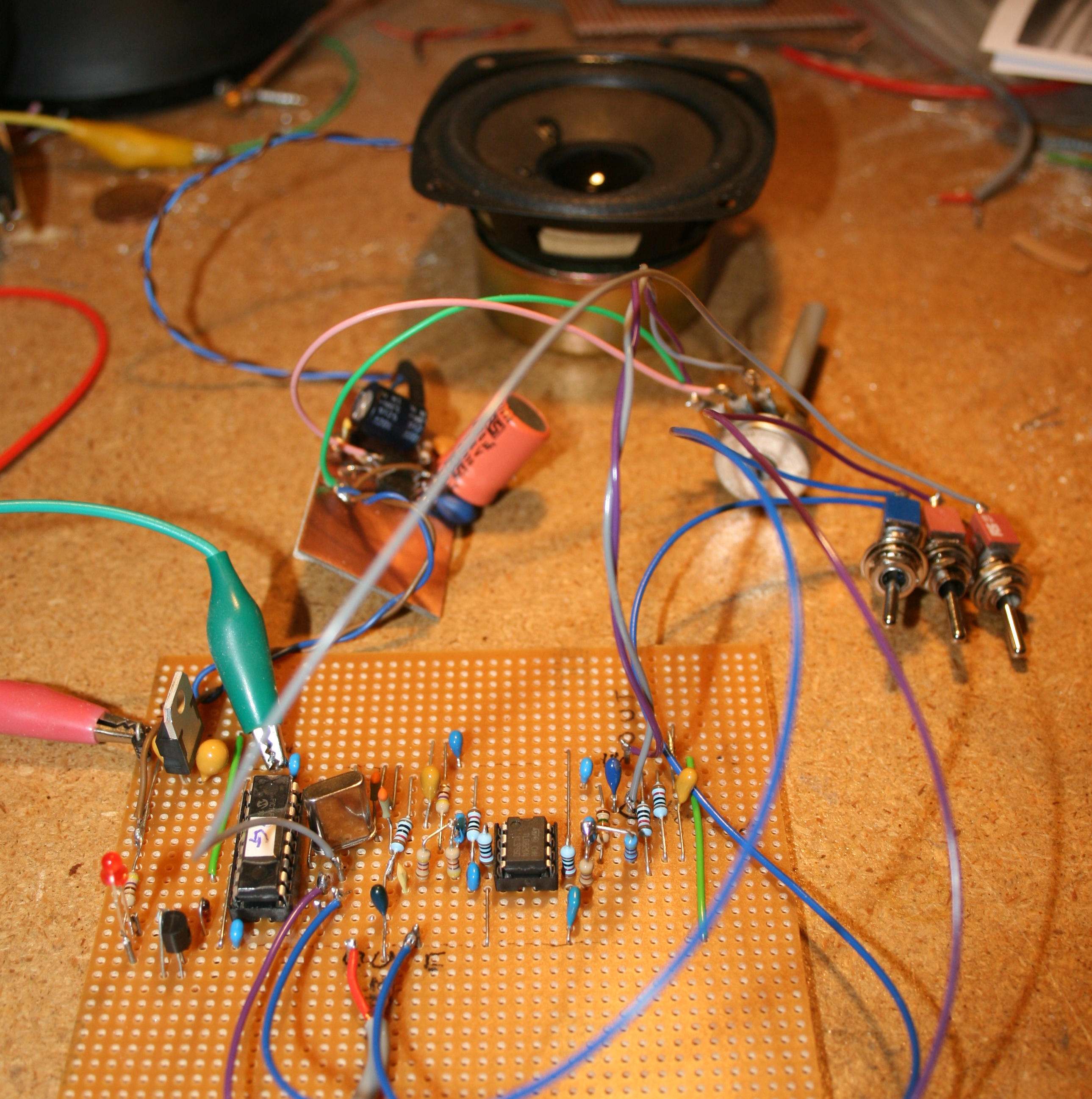
The construction of the comb filter is not critical and can be accomplished by a reasonably-experienced experimenter. As can be seen in Figure 3 different versions were built onto pieces of phenolic "prototyping" perfboard.
While there is nothing particularly sensitive about the overall layout it is recommended that interconnecting wiring be kept as short as practical - particularly around the microprocessor and its 20 MHz crystal. Some care be paid to the layout of the ground bus to avoid the possibility of "ground loops" - especially if you include a speaker amplifier - although at such low power levels and with fairly high audio signal levels this is unlikely to be too much of an issue. The most critical aspects of the layout have to do with the fact that capacitor C106 - the power supply bypass for the PIC - should be placed very close to the chip itself to minimize supply-voltage noise which could show up in the A/D conversion.
As shown in the schematic, this filter does not have an amplifier to drive a speaker as it is intended as a device to be place inline, between a speaker amplifier and the optical receiver. It may be built into its very own box with in/out connectors, or be incorporated directly into another box containing other circuits.
Additional notes on construction:
Since my version of the filter is still in its prototyping stage, it doesn't include several features that might be helpful were it to be used either as a stand-alone device or incorporated into another, larger system as Barry did.
- Bypass Switch: One of them is the aforementioned "bypass" mode in which the audio is simply passed from the PIC's A/D to the D/A converter. A nice addition would be a true "bypass" switch the entire comb filter out of the audio path. The reason for this has to do with the fact that the A/D and D/A resolution of the PIC - being only 10 bits - means that there's only about 50-55 dB of dynamic range available for audio signals - plus the fact that with a rather low sampling rate, it is necessary to limit the frequency response to 3 kHz or so: Having a "full bypass" switch removes the PIC from the circuit entirely for those occasions when you simply don't need it or the minor amount of degradation that it causes! If you really need the comb filter, that means that your signals are already degraded from the hum and despite the slight amount of degradation from the digitizing and the internal math, there will be a net benefit!
- Input level control: As shown in Figure 2, there are no provisions for an input level controls. For best performance in ANY digital-audio system, one runs the audio as "hot" as possible (below clipping, of course!) in order to maximize the available dynamic range and on a low-end processor such as this - with only 10 bits - this is arguably more important! Ideally, one should keep the audio level at the point where the "clip" LED flickers occasionally (or, perhaps, slightly more often) on audio peaks - but not high enough that there is audible distortion and not so low that the LED never flickers at all! To do this, an "input gain" control (and - possibly - an additional audio amplifier stage) would be nice to have. It should be noted that the peak audio level on the input of the as-drawn circuit is on the order of 1-2 volts peak-peak and it is assumed that whatever it is that you are feeding this filter with will be able to provide enough audio to satisfy this need - even with weak signals. Barry, when incorporating the unit, took this into account.
- Output level control: This is less critical as you probably would use this device with an audio amplifier anyway and can effectively adjust levels with the volume control!
- Mode switches: Practically speaking, only the "Bypass" pin would be connected to a switch as the others pins (e.g. 50/60 Hz, Sel1, Sel2) could be "hard-wired" for one's needs. If you do wish to select between different filter modes, there are two easy options:
- Use of DIP or front-panel toggle switches to select modes.
- The use of a 4-position rotary switch ground the
appropriate pins through diodes to select "bypass" or one
of the filtering modes.
On my workbench I was able to test it using the audio files provided by Barry to verify that it did, in fact, work on 100 Hz mains - although I had to make a minor change: It seemed that the field recording that Barry made was with a device that had a very slight (about 0.4 percent) sampling rate error and the comb filter's efficacy was initially rather disappointing. Upon realizing that there was a slight difference and the 100 Hz mains interference was slightly off-frequency, I used the Audacity program to re-sample the audio to put the hum precisely on-frequency and was gratified to note that the filter worked quite well! This warning serves to reiterate the importance of making sure that your sample rates are accurate - especially if you are going to re-process the audio files later and not use the same audio device for both record and playback!
Comments:
- In most countries the mains frequency is held to within a few 10's of milliHertz of nominal, so in-field use should not be affected by these frequency variations. If the source of light causing problems is from a portable power system - such as at a construction site - then the AC frequency from the generator may vary too far from nominal for the filter to work effectively!
- I have long-used a 1 kHz tone for testing and alignment,
but with a comb filter set up for 50 Hz mains, this may not
work as the 1 kHz tone is right on frequency because it is a
precise harmonic of the 100 Hz "hum" frequency! If you
use alignment tones in your field work - and plan to use a
comb filter - make sure that they do not land on exact
(within a few Hz) multiples of comb frequency or you may not
hear them! Needless to say, a 1 kHz tone is not
a problem with a comb filter configured for 60 Hz mains as
there is no integer relationship with 120 Hz and 1
kHz! The other option would be to make sure that if
you do use a 1 kHz alignment tone on with a
comb filter set for 50 Hz mains, that the filter be bypassed
or that the monitoring be done at a point prior
to the comb filter!
- Fortunately, mains-operated lightning has strong components located at intervals of twice the mains frequency - that is 100 or 120 Hz, depending on your area. If the efficacy of this filter is tested by coupling hum into an audio lead it's worth noting that doing this will introduce audio with components that are at the mains frequency and the filter won't seem to work very well since half of the spectral components aren't being filtered! If, for some reason, you did want to have a 50 or 60 Hz comb filter, the easiest way to do this would be to use a 10 MHz crystal instead of a 20 MHz crystal while noting that the audio sampling rate will be halved from 10 to 5 kHz and will likely cause aliasing distortion on the inputted audio! Since I have extra code space on the processor, I may add such a feature, activated by pulling a pin low, in the future.
- In testing, the notch depth was measured as being in the
area of 38-44dB depending on the filter mode. As may
be expected with only 10 bits of A/D and D/A along with
simple integer math, the signal-noise ratio of the entire
filter itself is on the order of 30-40dB but considering
that the detected signals will have already been somewhat
degraded and have a far lower signal-noise ratio than this,
the contribution of this filter is generally minimal.
The next step was to conduct field trials. Fortunately for me, Barry had immediate use for the comb filter on an upcoming outing and he reported that it worked very well as the following audio clip demonstrates:
- Audio File: G0EWN as received by G8AGN at Roper Hill via an 87km optical path using the comb filter. Note that this was recorded acoustically - that is, a microphone placed in proximity to the speaker. (1:08, MP3 format, 808kB)
What about an A/B comparison? At the time of writing, neither Barry or I have had time to do in-field "A/B" comparisons with and without the comb filter or selecting amongst its various modes, but here is a demonstration recording that I'd sent to Barry during the prototyping and initial testing of the PIC's code:
- Audio File: A sample of audio from the 66km test that has been passed through the comb filter in its various modes. During the file, various modes of the comb filter were selected - starting out in "bypass" mode with no filtering. Again, the original source material was via "microphone plus speaker" coupling. (1:08, MP3 format, 1040kB)
 |
Comments:
- This filter can also be used after-the-fact to filter
audio affected by mains harmonics. When recordings are
made, note the above comments about differing sampling
rates! If it is played back on the same device that it
was recorded, any errors will usually cancel
out, but if it is a recorded on a portable device and then
played back on a computer you should be prepared to adjust
the sample rate! If recordings are made using an
analog tape recorder you should be aware that normal speed
variations of the tape recording will likely make the use of
this comb filter ineffective on playback! Also, it is
unknown what affect various types of audio compression
schemes will have on the absolute frequencies of these
components, so un-compressed PCM (e.g. ".WAV") files are
recommended.
- My personal preference is to make in-field recordings with a minimum of filtering and processing as to avoid affecting later analysis - that is, any filtering is placed farther down-stream from the recording device. I figure that any filtering that I do in the field can be re-created back at home if necessary - assuming that I have a "good" quality "raw" recording to begin with - and for that, I record ONLY to un-compressed .WAV files - usually at 32 kHz. The caveat is, again, that the sampling rate of the record and playback devices may be different and that some adjustment may be necessary!
Final notes:
This comb filter has been shown to work in the field and as I get time to do so, I will do further testing and update this web page. If you are interested in building a comb filter such as this, feel free to let me know via the email link at the bottom of this page.
Contact me for details about this updated version if you are interested in this filter.
I plan to make additional enhancements to this circuit/code in the future - stay tuned.
Footnote:
- - Many narrowband optical filters have a fairly narrow angle of acceptance in which off-axis light is filtered differently than on-axis light in terms of filter loss and its wavelength and bandwidth characteristics. In a very simple lens system of small f/D ratio, the angle at which light may hit the filter could be beyond its specifications and thus affect response.
- - The "Blur Circle" of
the lens is the smallest point that can be focused.
For highly-accurate lenses made to sub-wavelength accuracy,
this is the so-called "airy disk"
and is limited by the small, but finite size of the
wavelength of light itself. For less-accurate lens
systems, this is known as the "circle
of confusion" or "blur circle." Fresnel
lenses - being comparatively inaccurate - can not achieve
accuracy to produce a true airy disk, so the smallest spot
size that they produce is that of the blur circle. It
makes sense, then, that if one were to focus the distant
light source using one of these lenses onto a detector that
was as large as the blur circle, one would - in theory -
intercept all of the light that had been focused by that
lens onto the focal plane. Using a detector that is
smaller than this causes some of the light to be thrown away
while an unnecessarily-large detector implies that adjacent
sources of light may also fall onto the detector - not to
mention the fact that a larger detector can introduce more
noise and capacitance effects than a smaller detector.
More on the relative sizes of blur circles produced by
inexpensive, plastic Fresnel lenses may be found on the "Fresnel Lens
Comparison" web page.
For more details of Barry's work, see G8AGN's Laser and LED pages where he and his friends have been doing optical communications experiments for several years now - first, with lasers, and more recently with high-power LEDs. A video clip from one end of the January, 2011 87km 2-way contact - which was believed to be a UK distance record at the time - may be seen here.
Return to the KA7OEI Optical communications Index page.
If you have questions or comments concerning the contents of this page, or are interested in this circuit, feel free to contact me using the information at this URL.
Keywords: laser pointer, laser, pointer, Lightbeam communications, light beam, lightbeam, laser beam, modulated light, optical communications, through-the-air optical communications, FSO communications, Free-Space Optical communications, LED communications, laser communications, LED, laser, laser voice, laser voice transmitter, laser voice communicator, laser communicator, laser transmitter, laser voice sender, laser pointer transmitter, laser pointer transceiver, laser pointer communicator, laser pointer communications, laser pointer voice communicator, laser pointer voice communications, light-emitting diode, lens, fresnel, fresnel lens, photodiode, photomultiplier, PMT, phototransistor, laser tube, laser diode, high power LED, luxeon, cree, phlatlight, lumileds, modulator, detector
This page and contents
copyright 2011-2015 Last update: 20150820